If you’ve ever watched one of these little machines crawl across a lawn on its own, turning corners like it actually knows where it’s going, you’ve probably had the same thought I did the first time I saw one up close: how does something this small figure out where to cut, when to stop, and how to avoid the flower bed without anyone touching a remote? The answer isn’t magic. It’s a stack of surprisingly clever engineering decisions layered on top of each other, and once you understand how they fit together, the whole idea of a MINI ROBOTIC TRACTOR LAWN MOWER stops looking like science fiction and starts looking like a very well-solved mechanical puzzle.
This isn’t a shopping guide. There’s no comparison chart, no “top five picks,” no pricing talk. What follows is a breakdown of how these machines are actually designed and built — the chassis, the sensors, the navigation logic, the cutting mechanism, and the manufacturing choices that turn a pile of parts into something that mows a lawn better than most humans would bother to.
The Chassis: Small Footprint, Big Engineering Problem
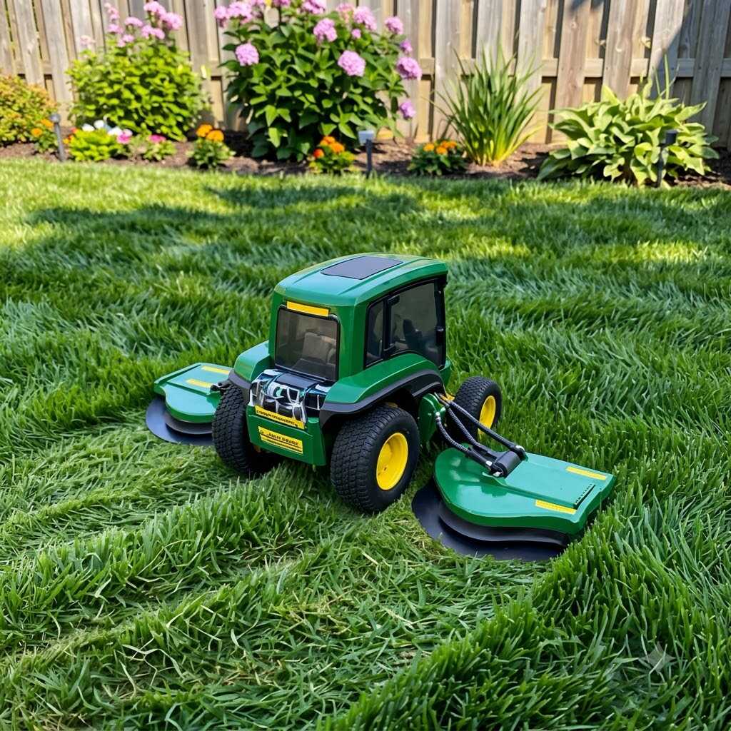
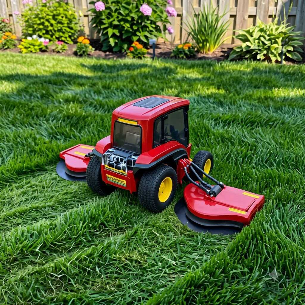
Calling it a “tractor” is a bit of a stretch in terms of size, but the label fits in spirit. These units are built low, wide, and heavy for their footprint, because stability matters more than almost anything else once the machine is working on a slope. Engineers designing the chassis have to balance three things that fight each other constantly: weight (for traction and stability), size (for maneuverability around obstacles), and material cost (because aluminum and reinforced polymer aren’t cheap at scale).
Most frames use a hybrid approach — a rigid internal skeleton, often stamped or extruded aluminum, wrapped in an injection-molded polymer shell. The skeleton carries the structural load: motors, battery pack, wheel axles. The shell handles weatherproofing and impact absorption. This two-layer approach is a manufacturing compromise as much as it is a design one; molding a single complex piece that does both jobs would be more elegant, but it’s also more expensive to tool and far less forgiving when something inside needs replacing.
Wheel geometry deserves its own mention. A lot of these mowers use a slightly asymmetric wheelbase — larger rear wheels, smaller steerable fronts — which mimics the turning behavior of a full-size tractor at a fraction of the scale. That’s not an aesthetic choice. It’s what lets a machine barely bigger than a household cat pivot in a tight radius without tearing up the turf.
The Sensor Stack: Where the “Smart” Actually Comes From
Here’s where things get genuinely interesting. A mowing robot’s intelligence isn’t concentrated in one part — it’s distributed across a handful of sensor systems that constantly cross-check each other.
- Boundary detection used to rely almost entirely on buried perimeter wire, and a lot of DIY builders still use this method because it’s cheap and reliable. A low-voltage wire loop buried an inch or two underground creates a magnetic field the mower’s coil sensors can detect, letting it know the instant it’s approaching the edge of the yard.
- Ultrasonic and infrared obstacle sensors handle short-range detection — the stuff boundary wire can’t account for, like a garden hose left out or a dog that wandered into the yard mid-cut.
- Inertial measurement units (IMUs) track tilt and orientation, which matters enormously on uneven terrain. If the chassis pitches beyond a safe angle, the cutting blade shuts off almost instantly. This single fail-safe is one of the most tightly regulated parts of the entire design process.
- GPS and RTK (Real-Time Kinematic) positioning show up in the more advanced builds, giving centimeter-level accuracy for mapping the yard without any wire at all. This is the technology that’s slowly replacing buried perimeter systems altogether, and it’s a fascinating shift in how these machines are engineered from the ground up.
None of these sensors work in isolation. The real engineering achievement is in the fusion logic — the firmware that takes noisy, sometimes contradictory data from four or five sources and turns it into one confident decision about where the machine is and what it should do next.
Navigation Logic: Random Isn’t as Random as It Looks
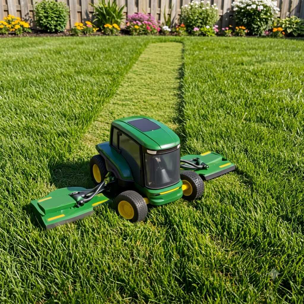
Early robotic mowers used what’s essentially a bounce-and-turn pattern — hit a boundary, pick a semi-random new heading, go until you hit something else. It looks chaotic, but it’s a deliberately simple algorithm because simple algorithms fail less often, and failure on a rotating blade is not something engineers take lightly.
Newer systems use systematic path planning instead — parallel stripe patterns, spiral coverage, or grid-based mapping that builds a mental model of the yard over the first few cutting cycles. This requires more onboard processing power, which is its own design tradeoff, because every watt spent on computation is a watt not spent on cutting or driving. Balancing battery life against processing complexity is one of the quieter but more constant tensions in this entire product category.
The Cutting Mechanism: Deceptively Simple, Precisely Engineered
The blade assembly looks almost too basic compared to everything happening around it — usually a set of small, pivoting razor blades mounted to a spinning disc rather than one large fixed blade. That’s intentional. Pivoting blades can swing backward on impact with a rock or root instead of transferring the full shock into the motor shaft, which dramatically cuts down on mechanical failure.
Cutting height adjustment is typically handled through a threaded post or a stepped cam mechanism, letting the deck raise or lower in small increments. Manufacturing tolerances here matter more than you’d think — even a couple of millimeters of inconsistency across a production run can create visibly uneven cuts, which is why blade-deck assemblies tend to go through tighter quality control checks than almost any other component.
Power and Manufacturing Considerations
Lithium-ion battery packs dominate this category now, largely because they allow for a lighter overall build and more predictable charge cycles compared to older lead-acid setups. The battery compartment is one of the most heavily sealed sections of the entire chassis, since it has to survive rain, sprinkler exposure, and the occasional puddle without a single seam failure.
From a manufacturing standpoint, these machines are a good example of design for assembly (DFA) principles in action — snap-fit housings, modular sensor boards, and standardized fastener types that reduce both production time and the tools needed for field repairs. It’s a small product category, but it borrows heavily from automotive and consumer robotics manufacturing playbooks.
Wrapping It Up
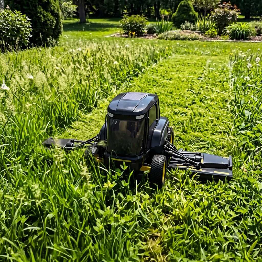
What makes a mini robotic tractor lawn mower genuinely smart isn’t one single breakthrough — it’s the accumulation of small, deliberate engineering choices working together: a chassis built for stability over size, a sensor stack that cross-verifies its own data, navigation logic that trades complexity for reliability, and a cutting mechanism engineered to survive its own mistakes. Understanding how all these pieces fit together changes how you look at the machine entirely. It’s not autonomous because of some single clever trick. It’s autonomous because a lot of people spent a lot of time making sure each individual system could be trusted to do its one job well, every single time, without supervision.